Individual task description
Group task description
Summary of the week
I wanted to get more familiar of the possibilities ESP82666
Because my final project will use ESP8266 as a main unit, I wanted to continue my explorations with it (earlier I have used it e.g. in embedded programming. Due to my other responsibilities during covd-19, my documentation is lagging behind, but I am doing my best (to write it). However, I have been reading tutorials and trying to learn ESP.
Although I knew that just using ESP8266 and sensors/actuators would have been enough for this week's assignment, I wanted add also wireless communication between devices. In my final project mobile headset (AI software) and ESP32 will communicate wirelessly, so I wanted to learn those features in this task
In this documentation I will demonstrate how to control ESP8266 outputs and display sensor data from the ESP8266 on Node-RED. The Node-RED software is running on a Raspberry Pi, and the communication between the ESP8266 and the Node-RED software is achieved with the MQTT communication protocol.
First phase: Installing the required software
Getting started with Node-RED on Raspberry Pi
First you have to get familiar what is Node-RED and how to install it to your Raspberry Pi. In my documentation I suppose that you are familiar with Raspberry Pi and how to install programs to it. If you don't, please go to https://randomnerdtutorials.com/getting-started-with-raspberry-pi/getting started tutorial to learn how to install operating system and use the device.
--- introduction picture -- (what is node-red)
What is Nodered and What can you do with Node-Red
Node-red is open source platform, which allows to prototype complex systems quickly. With node-red it's possible to make cool stuff easily, rather than spending hours and hours writing code. See examples here: https://flows.nodered.org/
For exaample, its easy to:- Access your RPi GPIOs
- Establish an MQTT connection with other boards (Arduino, ESP8266, etc)
- Create a responsive graphical user interface for your projects
- Communicate with third-party services (IFTTT.com, Adafruit.io, Thing Speak, etc)
- Retrieve data from the web (weather forecast, stock prices, emails. etc)
- Create time triggered events
- Store and retrieve data from a database
Installing Node-RED
Getting Node-RED installed in your Raspberry Pi is quick and easy. It just takes a few commands. Having an SSH connection established with your Raspberry Pi, enter the following commands to install Node-RED:
pi@raspberry:~ $ bash <(curl -sL https://raw.githubusercontent.com/node-red/raspbian-deb-package/master/resources/update-nodejs-and-nodered)
To automatically run Node-RED when the Pi boots up, you need to enter the following command:
pi@raspberry:~ $ sudo systemctl enable nodered.service
Now, restart your Pi so the autostart takes effect:
pi@raspberry:~ $ sudo reboot
When your Pi is back on, you can test the installation by entering the IP address of your Pi in a web browser followed by the 1880 port number:
http://192.168.100.47:1880 (my case)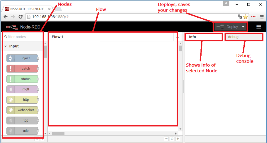 >
>
Installing Node-RED dashboard
To install the Node-RED Dashboard run the following commands:
- pi@raspberry:~ $ node-red-stop
- pi@raspberry:~ $ cd ~/.node-red
- pi@raspberry:~/.node-red $ npm install node-red-dashboard
Then, reboot your Pi to ensure that all changes take effect on Node-RED software:
pi@raspberry:~ $ sudo reboot
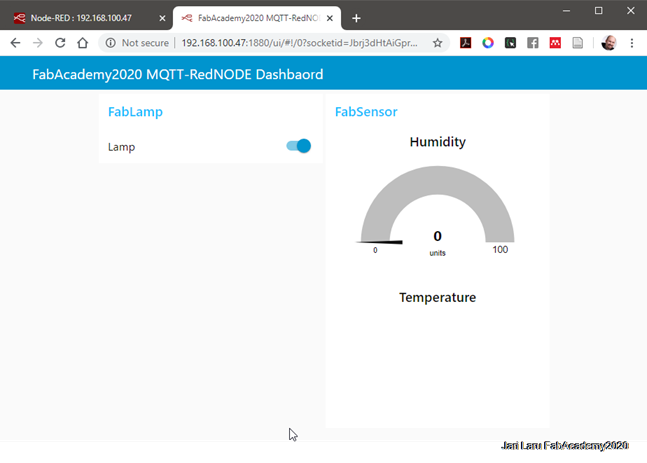
To open the Node-RED UI, type your Raspberry Pi IP address in a web browser followed by :1880/ui as shown below:
http://192.168.100.47:1880/ui
Normally your dashboard is empty, because we haven’t added anything to the dashboard yet. In my case I have taken greenshot later on, so I have user interface done by me
Getting started with MQTT-protocol
MQTT stands for MQ Telemetry Transport and it is a nice lightweight publish and subscribe system where you can publish and receive messages as a client. It is a simple messaging protocol, designed for constrained devices and with low-bandwidth. So, it’s the perfect solution for Internet of Things applications.
What is MQTT and How It Works: https://randomnerdtutorials.com/what-is-mqtt-and-how-it-works/
Installing Mosquitto Broker
In MQTT, the broker is primarily responsible for receiving all messages, filtering the messages, decide who is interested in it and then publishing the message to all subscribed clients.
There are several brokers you can use. In this tutorial we’re going to use the Mosquitto Broker which needs to be installed on Raspberry Pi.
To install the Mosquitto Broker enter these next commands:- pi@raspberry:~ $ sudo apt update
- pi@raspberry:~ $ sudo apt install -y mosquitto mosquitto-clients
You’ll have to type Y and press Enter to confirm the installation. To make Mosquitto auto start on boot up enter:
pi@raspberry:~ $ sudo systemctl enable mosquitto.service
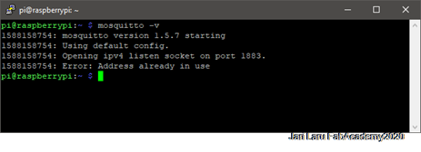
Sent following command to test installation:
pi@raspberry:~ $ mosquitto -v
This returns the Mosquitto version that is currently running in your Raspberry Pi. It should be 1.4.X or above.
Note: I took this screenshot in the context where I already had mosquitto instance running. So mosquitto -v prompts a warning message saying “Error: Address already in use“. That warning message means that your Mosquitto Broker is already running, so it is ok.
Second phase: Establishing an MQTT communication with Node-RED
In this section I am going to describe how to establish an MQTT communication using the Node-RED nodes. MQTT is bridge between Raspberry Pi (Node-RED server) and ESP8266 (client, which does measure temp and humidity, but also controlles light (LED)
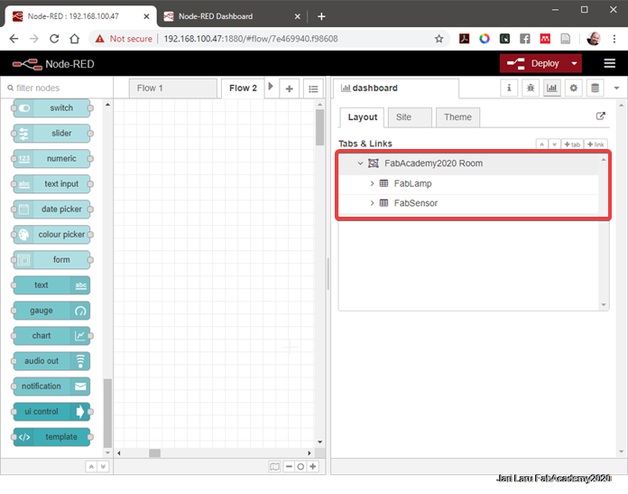
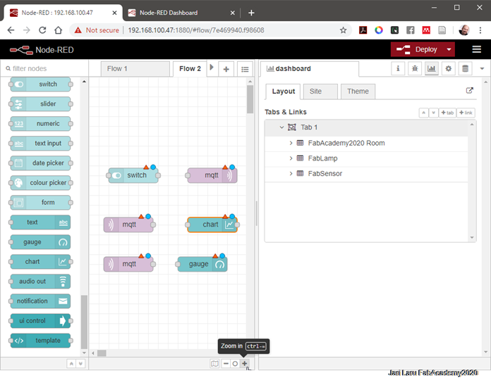
Step 1. Create dashboard layout
The first step is to create the dashboard layout. In this example, we’ll have a button to control an ESP8266 output; a chart and a gauge to display temperature and humidity readings from the DHT11 sensor.
On the top right corner of the Node-RED window, select the Layout tab under the dashboard tab. Create a tab called Room and inside the Room tab, create two groups: Lamp and Sensor as shown in figure below.
Step 2. Create the flows
Drag the following nodes to the flow:
- switch – this will control the ESP8266 output
- mqtt output node – this will publish a message to the ESP8266 accordingly to the switch state
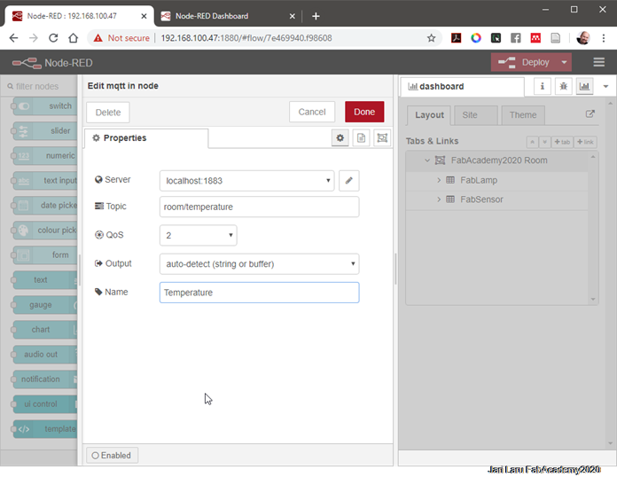
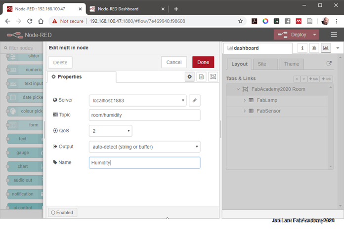
- 2x mqtt input nodes – this nodes will be subscribed to the temperature and humidity topics to receive sensor data from the ESP
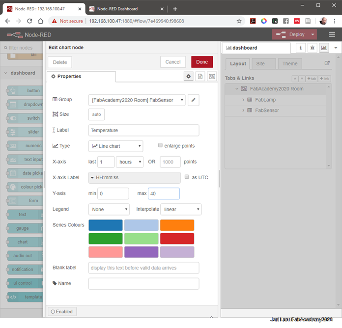
- chart – will display the temperature sensor readings
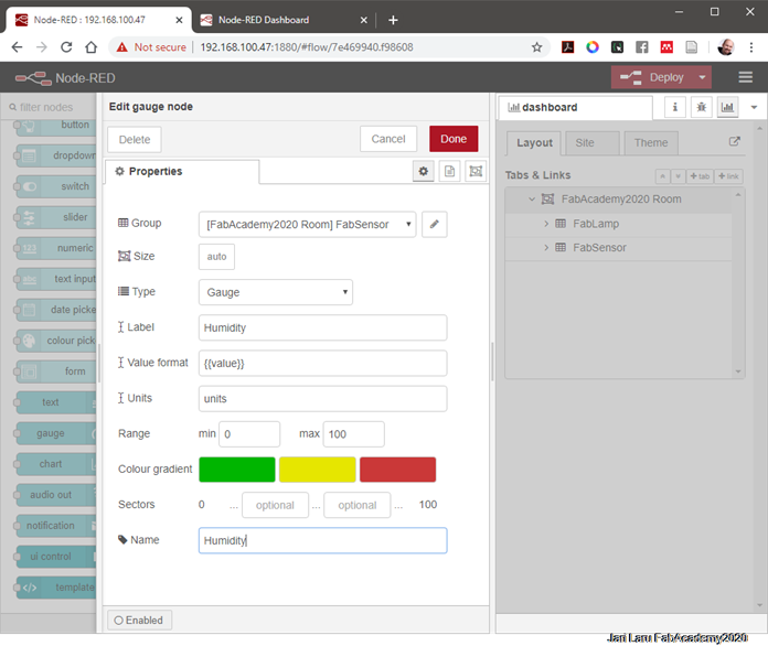
- gauge – will display the humidity sensor readings
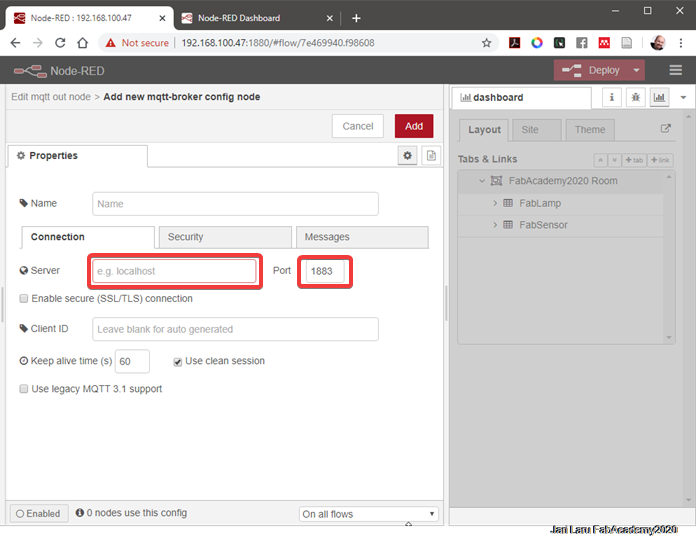
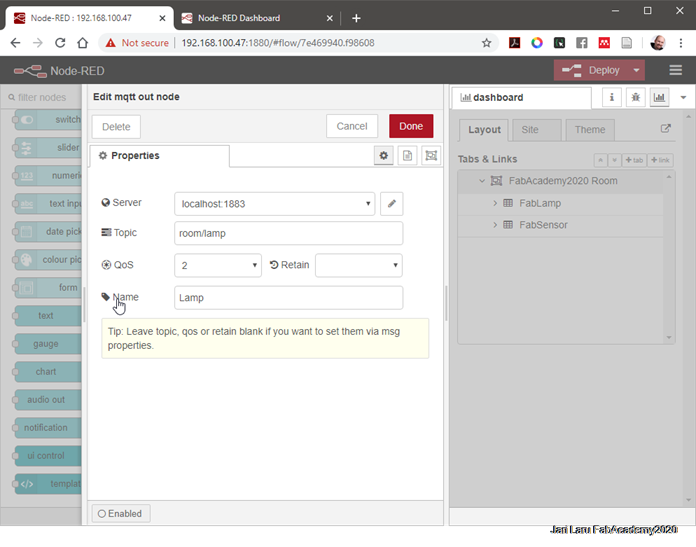
Node-RED and the MQTT broker need to be connected. To connect the MQTT broker to Node-REd, double-click the MQTT output node. A new window pops up – as shown in figure below.
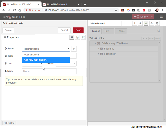
- Click the Add new mqtt-broker option.
- Type localhost in the server field
- All the other settings are configured properly by default.
- Press Add and the MQTT output node automatically connects to your broker.
 Edit all the other nodes properties as shown in the following figures:
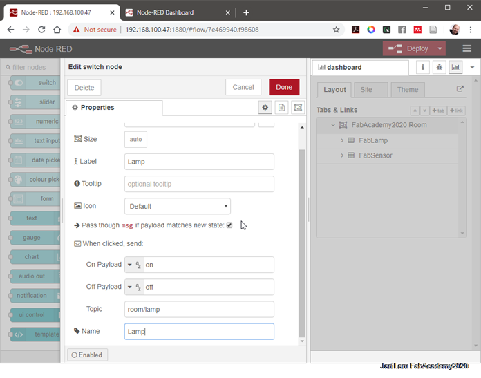
Wire your nodes as shown in the figure below. and then click the "deploy" button on the top right corner. The Node-RED application is ready. To see how your dashboard looks go to: http://your-pi-ip-address/ui.
http://your-pi-ip-address/ui.
Third phase: Preparing your Arduino IDE
ESP8266 works in my context as a platform for transferring temperature and humidity measurements to Raspberry Pi. It also turns on/off LED, which is an example of lights. So in practise, one can follow temperature/humidity from distance AND control lights by using www-browser or mobile phone
In this phase you will see how to program the ESP8266 by using the Arduino IDE. In order to upload code to your ESP8266 using the Arduino IDE, you need to install the ESP8266 add-on (This will be explained in the section: embedded programming). You’ll also need to install some additional libraries to have everything ready for your ESP8266.
Libraries needed in my case
PubSubClient Library
The PubSubClient library provides a client for doing simple publish/subscribe messaging with a server that supports MQTT (basically allows your ESP8266 to talk with Node-RED).
- https://github.com/knolleary/pubsubclient/archive/master.zipClick here to download the PubSubClient library. You should have a .zip folder in your Downloads folder
- Unzip the .zip folder and you should get pubsubclient-master folder
- Rename your folder from pubsubclient-master to pubsubclient
- Move the pubsubclient folder to your Arduino IDE installation libraries folder
- Then, re-open your Arduino IDE
The library comes with a number of example sketches. See File >Examples > PubSubClient within the Arduino IDE software.
Library for BME280 sensor
To install the library navigate to the Arduino IDE > Sketch > Include Library > Manage Libraries… Wait for Library Manager to download libraries index and update list of installed libraries.
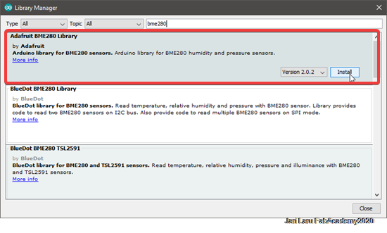
Filter your search by typing ‘bme280’. There should be a couple entries. Look for Adafruit BME280 Library by Adafruit. Click on that entry, and then select Install.
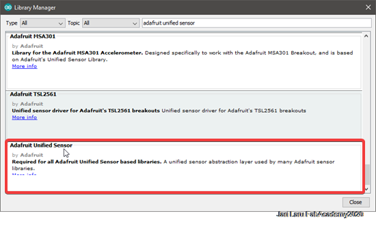
The BME280 sensor library uses the Adafruit Sensor support backend. So, search the library manager for Adafruit Unified Sensor and install that too (you may have to scroll a bit)
Selecting the right board on Arduino IDE
To see more about these settings, please navigate to embedded programming section, where I do describe these basics
Upload the code to ESP8266 via Arduino IDE
Now, you can upload the following code to your ESP8266. This code publishes messages of the temperature and humidity from the BME sensor on the room/temperature and room/humidity topics trough MQTT protocol.
The ESP is subscribed to the room/lamp topic to receive the messages published on that topic by the Node-RED application, to turn the lamp on or off.
You need to edit the code with your own SSID, password and RPi IP address.
Download the code: FabAdademy2020_FIN_app_interfaces_laru.ino
//// IMPORTANT NOTICE (Fab Academy 2020 / Laru
//// This code is a remix of following projects done by others:
/// 1. https://randomnerdtutorials.com/esp8266-and-node-red-with-mqtt/ (how to use MQTT and Nodered, but NOT how to use DIT sensor, because i didn't have that component)
/// 2. https://lastminuteengineers.com/bme280-esp8266-weather-station/ (to learn how to use BME sensor, because I didn't have DIT sensor)
/// Libraries that I used to use BME sensor didn't have function to compute heatindex, so I have disabled it from this code below.
#include
Monitoring the execution of the code by using Serial monitor
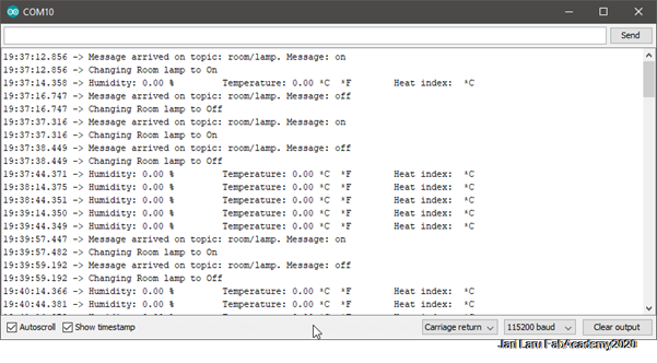
After uploading the code, and with the Raspberry Pi running your Node-RED application and the Mosquitto broker, you can open the Arduino IDE serial monitor at a baud rate of 115200 and see what’s happening in real time.
This is helpful to check if the ESP has established a successful connection to your router and to the Mosquitto broker. You can also see the messages the ESP is receiving and publishing.
From the console window below, it's easy to recognize that ESP8266 and Raspberry Pi are communicating well, but temperature measures are not working as those should. In the next phase circuitry of the project is presented and tested
Fourth phase: Building the Circuit
The following sections show you the needed parts and schematics to build the circuit for this project.
Parts required
These are the parts required to build the circuit:
- Raspberry Pi – read Best Raspberry Pi 3 Starter Kits
- ESP8266 (ESP-12E nodemcu)
- BME temperature and humidity sensor
- Breadboard
- 330 Ω resistor
- LED
Designing the circuitry for the project
Because of the Covid-19 I have used breadboard for this exercise. In order to design and demostrate circuitry in my case, I did use Fritzing tool.
"Fritzing is an open-source hardware initiative that makes electronics accessible as a creative material for anyone." (https://fritzing.org/home/)
I used Fritzing app to draw both schematics of the connections and breadboard layout. Tool would be used also a planning tool for PCB design, but in the context of Covid-19 I can't design my own pcb. I am also pretty happy to use breaboard together with Frizting, because I see very nice possibilities to extend this combination to my courses in the Faculty of Education. Fritzing is very user friendly tool and visualizes electronical connection very well.
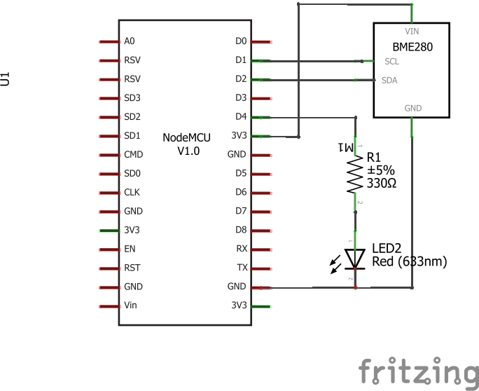
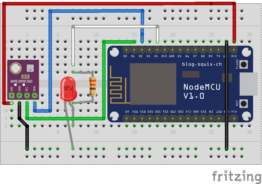
Below you can see schematics where four components are wired together: LED, resistor, environmental sensor (BME) and ESP82666. Breadboard version of the same theme is used to demostrate wiring. How you need to wire components together to get everything rock together
In practise, BME sensor uses I2C bus for data transmission (SCL and SDA on schematics and green and blue cords on breadboard figure. In addition to that it needs power source and ground to be used. In addition to that, LED, which is an example of remote controlled ligts in my case, is connected to GPIO output (D4) of the ESP8266 with white wire (where is resistor for controlling the current before LED). Such ballast resistor is used to limit current flowing through LED and to prevent it burns.
Fifth phase: Finalizing the UI and functionalities, but also Debugging non-functional features
Debugging, debugging, debugging and debugging
I got my first impression about Node-Red and MQTT from my cousin who works in the field of software engineering and IoT. So I had "some ideas before this assignment". Also our local instructor, Antti Mäntyniemi gave hints about using Node-Red and MQTT. I had also personal interest to learn how to integrate ESP platform via wifi to other tools and technologies, because in my final project I will rely on integration between ESP32 and smartphone.
Although combination of simple eletronics and MQTT-Node-red traffic seems to be pretty simple to build and operate, there are a lot of caveats that I did encounter during tinkering with the software and hardware components. Biggest obstacle for "smooth" end result was the fact, that I did compensate my limited programming experience on C-language with remixing existing projets together
So, being beginner, I had to follow existing tutorials and documentations to learn how to integrate these different technological parts together
- First project was complete tutorial of using Node-Red, MQTT and ESP8266 together to measure temp and control LED: https://randomnerdtutorials.com/esp8266-and-node-red-with-mqtt/
- Second project was about to build stand-alone weather station by using ESP8266: https://lastminuteengineers.com/bme280-esp8266-weather-station/
First tutorial was perfect fit for my purposes, except sensor used in this tutorial was different (DIT) than I had in my inventory (BME). So in order to get my BME sensor to integrated my project, I had use that second tutorial also to get ideas and examples.
Remixing of those two tutorials and limited timeframe led me to numerous of debugging events. Above I will highlight some of those.
Temperature measurements doesn't work, but LED light works
One of the issues that I had to debug was the fact that MQTT message exchange works perfectly, but ESP8266 doesn't measure temp and that's why MQTT messages are empty and Node-RED dashboard doesn't show any temperature and humidity related values
This was easy to see just by following acvities from serial monitor -window (picture below)
Because I had to adjust codebase by remixing two tutorials together and main code base was written by following tutorial where sensor was DIT-based, I got first series of error messages from Arduino IDE. Of course I knew this already, but because sensors were different, also needed code was different
I sorted those messages out, for example by definining Adafruit_BME280 bme; sensor, and starting the sensor bme.begin(0x76);
However, before I understood that I have to define BME sensor and start it by using hex code (adress of sensor in I2C bus) I had a lot of wrong ideas how to fix the issue. For example, I checked cables and pins of the ESP8266 multiple times. Most difficult thing was the fact, that I got code working well even without defining and starting BME. Somehow I managed to run code without starting BME at al all.
Anyway, eventually I got knowledge from different tutorials and found how to configure BME sensor
When LED is turned on, measurements will get very wrong values
Second debugging was done in the context where BEM sensor goes wild, when LED is activated. This was pretty "funny" because of temp decreased to -142 degrees and humidity was 100% until I did turn off lED
I almost understood that this is now issue which can be tracked to circuitry of BEM sensor and LED lamp. When I took I2C bus into use by adding it into C-code issue started. Somehow LED GPIO will mess I2C bus when LED is high.
Well, final solution was found from C code and it was pretty simple. I had tried different values to take GPIO for LED into use, while I was learning how to lit LED. When I took I2C bus into use I accidentally had value for LED GPIO Out in C-code which was in the conflict with I2C bus (D2 in ESP8266)

Figure: What did happen when I did turn LED on for temperature and humidity
Very very very embarrassing issue to be debugged: two parallel sketches compiled randomly
This was pretty weird issue, because code in Arduino IDE did change: sometimes I found that I have to write again changes, that I already had done.
Of course I thought that somehow I haven't saved my code and I have just lost my edits. But pretty soon I understood that I had earlier and current version of sketches available in separate windows. And Because I am who I am, I just randomly edited and compiled one of the parallel sketches
This is pretty typical "human error" in coding and was easily debugged when I understoond that I have to little bit elaborate my practises. This was solved by closing parallel sketch.
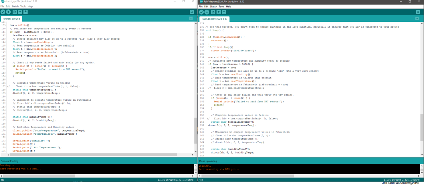
Figure: In this you can see how I had two "identical" sketches running on.
Finalizing the UI and Layout on Node-Red server
In order to increase at least little bit "professionalism" in this assignment I did small changes in my Node-Red configuration (new version of UI is also presented above in the second debugging example):
- I added realtime view to temperature
- I added trend data to humidity
- I regrouped both measurements into own groups
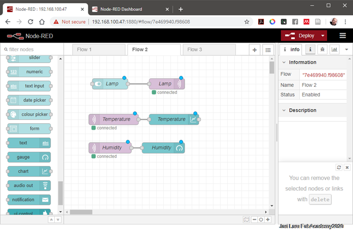
- In order to get those views working, I also needed to re-route data from MQTT intake(s) to respective Node-RED components by changing the flow (see picture below)
In addition to that, I also finetuned settings for y-axis in both charts. Y-axis of temperature chart got 18 celcius as minimum value and 34 as maxium temperature, while humidity chart got 25% as minimum value and 40% as maximum humidity. With such settings both graphs are more readable because of the more meaningful scale of the axis.
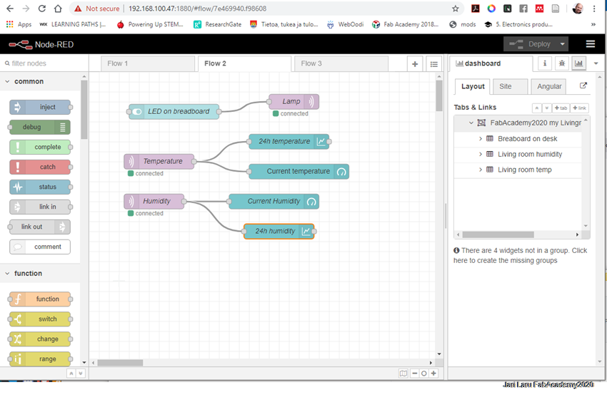
Figure: I added two new nodes: 24h humidity and current temperature, which are repsented in this diagram
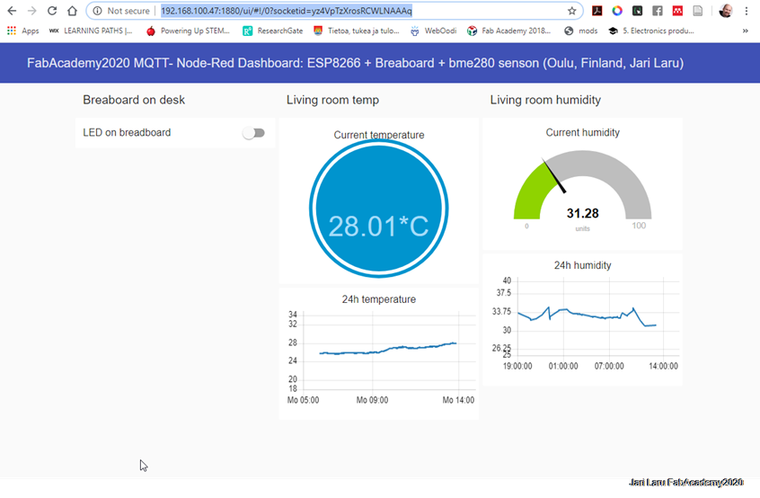
Figure: In this dashboard you can see changed Y-axes and new realtime temp and humidity trend graph
Video demonstrator of working project where erros and issues were ironed out
In the gif animation below you can see my project in the action. When I switch lamp on, LED turns on and Arduino IDE console shows how temperature measurements are collected and communicated a via MQTT
Summary and Reflections
I was surprised how easy it was to get ESP8266 to communicate with external server by using MQTT as communication channel. Even more easier it was to use Node-Red to build simple user interface for this purpose
I wanted to practise wifi communication between ESP-platform and other systems, because my final project is build around of the idea to use ESP32, but integrate it with mobile phone via wifi
In the future I will use ESP32 NODEMCU:s together with http://www.hass.io home automation. I already have explored tutorials how to integrate ESP32 as a part of integrated HA experience. In that case user interface will be provided by hass.io, alhough is pretty similar than Node-Red UX was.